Sphere Seas Coaxial (2009)
17. Dezember 2021 - Lesezeit: 10 Minuten
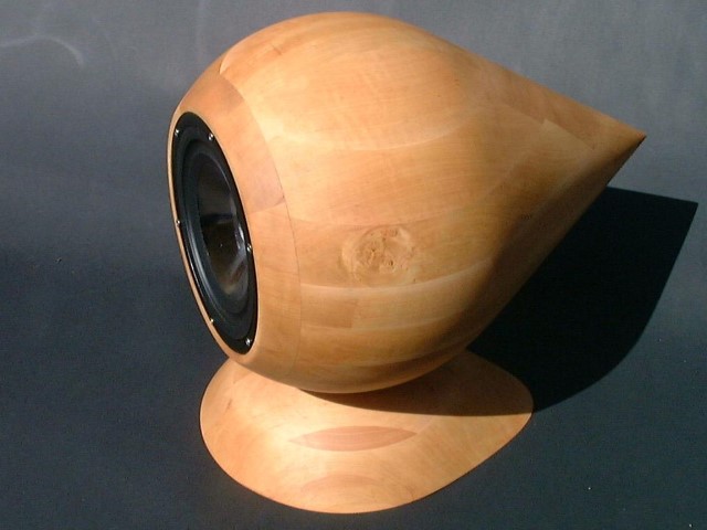
Having worked with Tannoy monitors in the studio for several years (TANNOY little RED12), the challenge of building a coaxial system was of course as near as pre-programmed. After Seas had launched the H1333 (no longer in production), at reasonable cost, a suitable cabinet was needed. The most basic would be the usual box in the 5-8 litre range, but if it had to be coax and point source, then the rest should also be tuned to a phase-optimised cabinet as much as possible.
To say it first place: without CNC and 3D CAD the Sphere cabinet is almost impossible to create.
In a coax setup, the excursion of the midrange-bass chassis should be moderate, otherwise the cone will cause intermodulations of the high frequency spectrum. Therefore, only a closed system with a high rolloff in the bass range will do.
With a 120 cm2 membrane area from a 6" driver, a huge low frequency response should not be expected. Air molecules need to be excited with sufficient cone area, so bass tuning is always depending on the indendent use for the system. A woofer extension is mandatory for this design. See Seas L22 MK1.
| System | Sphere |
|---|---|
| Topology | 2-Way passive (add active Woofer for full repsonse) |
| System sensivity | 85 dB @1m / 2.85V |
| Power handling | 60 watts |
| Impedance | 6 Ohm minimum @ 240Hz |
| Crossover | 2.1kHz 2nd order LR2 |
Driver
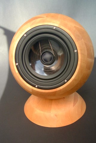
There is not much choice in coax chassis in this size, and I have had good experiences with SEAS chassis so far. The manufacturing quality is very good, as always with Seas, but I would have appreciated a little more care in adjusting the transition from the tweeter to the cone. The coil former is longer than it needs to be, and the edge of the tweeter is not level with the edge of the cone.
Data Sheet: Seas H1333
Enclosure
Building such an enclosure was first and foremost an experiment, and without the use of a CNC router, the whole thing would probably have failed. The sandwich construction and the use of solid wood also created a unique design approach. Based on the TS parameters, a volume of about 8 to 9 liters should be adequate.
The starting point is the impedance measurement of the woofer in free air (blue) and in a test cabinet(black). I only trust the data sheets to a limited extent, and prefer to rely on my own measurements.
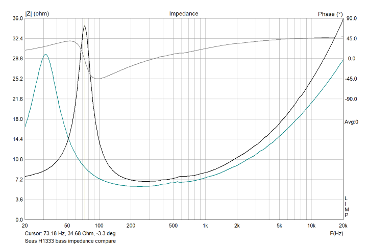
Since I have chosen a passive crossover network for this design, the rise of the impedance curve must be linearized to maintain an overall resistive characteristic at higher frequencies so that the performance of the crossover network is not compromised.
I have been using VituixCAD by Kimmo Saunisto for some time, a comprehensive program that covers all relevant calculations and simulations.
Crossover
The choice of crossover topology has a huge impact on sound we get from a system. Even if we produce the same frequency response from 1st, 2nd or 4th order filters and they may be Butterworth, Linkwitz-Riley, Bessel etc. they all sound very different.
This crossover was planned as an LR2 design as simple as possible . The tweeter response cleans up off axis, and will need to be crossed over below the point where the woofer begins to beam. After some tests an LR 2nd order topology with the crossover-frequency around 2.1kHz works fine. The woofer gets by with a single moderate size coil L1 and capacitor C1 and impedance flattening circuit C2 / R3. The tweeter path has an L-Pad R4 / R5 for level matching reasons.
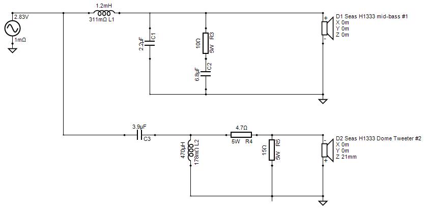
Important: Since the crossover is 2nd order, the tweeter is hooked up in reverse polarity with the positive terminals going to ground. Because we are dealing with a coaxial driver the centre X and Y position for woofer and tweeter are identical. However, as the tweeter resides in the centre of the woofer cone, it is offset by 21mm on the z axis.
Components were worked out between myself and and a good friend (GH), with better quality caps in the direct path and electrolytics in non-critical locations.
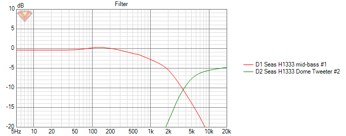
What you see here are modeled individual filter roll-offs, without driver parameter involved. The 5dB lower HP results from the L-PAD in the tweeter path.
Measurement
Measurements can show threshold values or a behaviour that allows an evaluation of the system. What measurements cannot tell you is the quality of tonal reproduction and the sonic imprint of a component. Therefore I use measurements to check threshold values, and with impedance-, frequency- and time alignment methods we have procedures at hand who can deliver comparable results.
But as soon as we put a loudspeaker in a room the real tuning starts. See also the blogs about room acoustics here. For DIYers, there is usually no anechoic room available, and the coupling with near-field measurements in the low end region are more wishful thinking than reality.
The first thing I do is verify the SPL limits and the associated excursion in the corresponding enclosure ( these are modeled data).
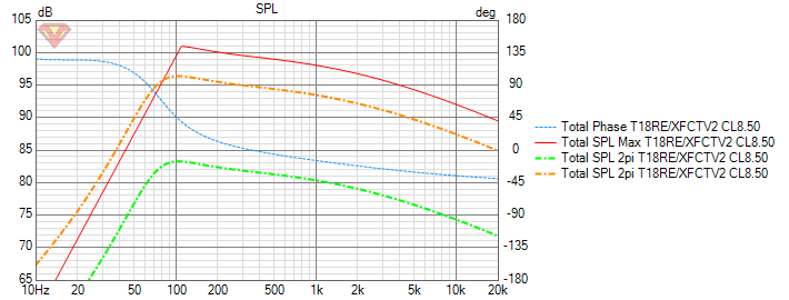
Actual SPL level @ 1 meter distance and 2.83V input is useful for an estimation of system sensitivity and combined with the impedance profile may give an idea of how powerful an amplifier should be to drive this speaker. In this case we get approximately 84dB SPL (green curve / ref Level ) and 96dB SPL (orange curve / 15W) we already exceed the limits of the driver in the bass range below 100 Hz.
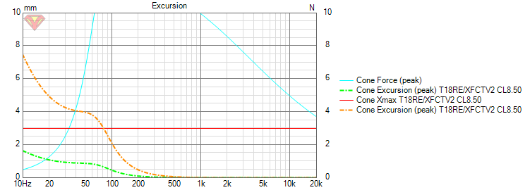
The same data can be seen in the excursion diagram. The limit for a linear excursion lies at +/- 3mm (red line / Xmax). It is obvious that we have to limit the cone excursion at 80Hz in the bass range.
Final system response with filter in place and nearfield measurement. For the tuning of the phase coherence, a compromise has to be found for the measurement that excludes room influences as far as possible and still reproduces the measurement angles in a similar position as the later listening distance. The dip @ 9kHz is typical for coax chassis, and can't be avoided. The 5 dB increase in the 100-500Hz region comes mainly from the baffle load of the cabinet and is compensated for later with the 4pi environment.
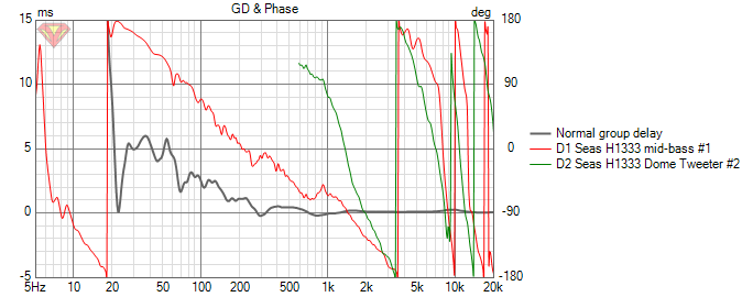
One of the advantages of coaxial systems is that woofer and tweeter are already mounted time aligned. To my experience a true 2nd order filter from time-aligned drivers sound better than the typical 2nd/3rd order filter and it requires fewer capacitors in series with the tweeter. With DSP/active crossovers you can compensate the difference in acoustic depth by inserting a delay, but this is not the goal here.
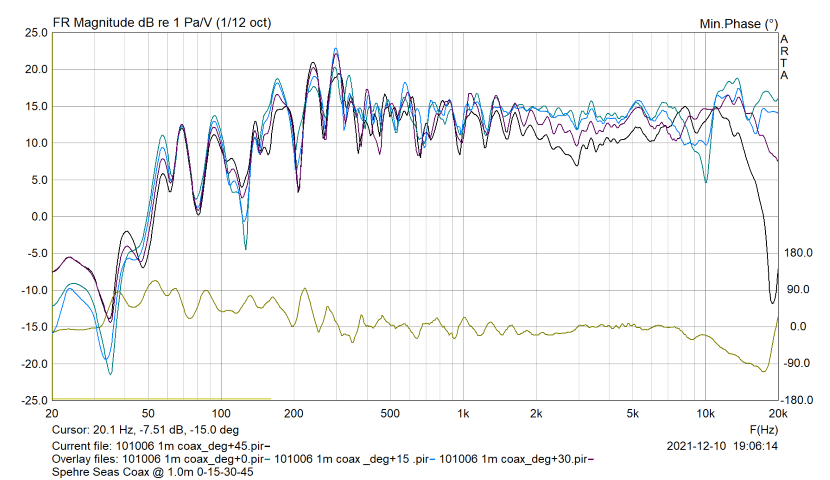
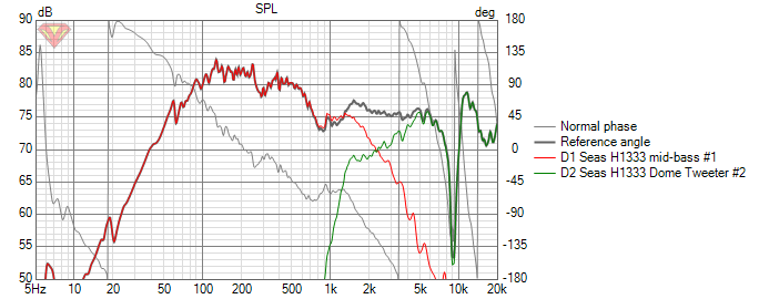
Frequency response for 0-15-30-45 degrees @ 1m. Room mode influence up tp 150Hz. The measured response is always a dose of reality compared to the modeled response. There are no abnormalities in the crossover region and the dispercion stays within +/- 2.5 dB over the critical mid band. The off axis curves gives a little more insight into what can be expected from a coax chassis. I did have to use my ears to make sure I had the relative levels correct between tweeter and woofer.
The dip @ 9kHz flattens out almost perfectly a few degrees off axis. You don't have to have the tweeters pointing directly at you in this design. Generally it's not going to matter much if the tweeters are toed in or not.
Room placement
Nothing too out of the ordinary here, and my recommendations are similar to my other systems. The design listening axis is the tweeter, and the design distance is 2.5 meters. Keep the rear of the enclosure at least a 40cm out from the back wall and approximately more than 90cm from the side wall. The woofer's room placement dimensions should be as different as possible and not even multiples of each other for the smoothest in-room mid-bass response.
Summary
It does sound very balanced in small and medium sized rooms, and a little lean in large rooms. What has surprised me the most is the sound stage depth and spaciousness from such a small design. Due to the coax setup of the drivers you get a rock solid phantom center and a large sweet spot. The addition of a sub-woofer is, in my opinion, mandatory so that the range up to 80 Hz can be reproduced adequately.